Run Test Recovery of vSphere Replication based Recovery Plan

VMware SRM recovery plan to handle a planned migration or other can be created only to recovery specific application or services by only including specific protection groups as part of the recovery plan. Recovery plans can be used for Test recovery, planned migration to the recovery site or for disaster recovery.In my previous article, I have explained the step-by-step procedure to create vSphere Replication based Recovery Plan in VMware SRM. In this article, I will explain the detailed procedure to validate the recovery plan by running Test recovery of vSphere Replication based recovery plan.

SRM Test recovery is nothing but a testing a recovery plan exercises with every aspect of the recovery plan. Site recovery manager ensures that test recovery will avoid disruption in ongoing operations of the protected and recovery site.

You can run SRM test recovery at any time.Running SRM test recovery does not disrupt replication or ongoing activities at either site. It is always recommended to run recovery plan test as often as needed to ensure that your actual DR plan is working as expected.

Perform Test Recovery of vSphere Replication based Recovery Plan

You can run the test recovery of vSphere Replication based recovery plan once all the SRM configuration is done. To run test recovery, Login to vCenter Server using vSphere Web client -> Site Recovery Manager -> Sites-> Recovery Plans -> Select the recovery plan -> Monitor -> Recovery Steps -> Press Green Play button to start the test recovery of vSphere Replication based recovery plan.

Once you have clicked on the Green Arrow button to start the SRM test recovery,  recovery will run in test mode and it will recover the virtual machines in a test environment on the recovery site.

You have storage option whether to replicate recent changes to the recovery site or not. This process may take several minutes to complete the replication of recent changes to the recovery site using vSphere Replication.

It is up to you run the test recovery with recent changes or not.  I have selected the option to replicate recent changes to the recovery site. Click on Next.

Review your settings selections before initiating the SRM Test Recovery and click on Finish.

Once SRM test recovery is executed, you will be able to see the series of test steps involved as part of this recovery plans and its progress percentage. Since I have selected the option to “Replicate recent changes to recovery site”, I can see that Synchronize Storage is completed and followed by other steps.

Once test recovery is completed, You can see the Plan status will display “Test Complete”. and status of each recovery steps will be Success.

Each recovery steps in recovery plan will have substeps involved. For example, When i expand the Power on VMs will have around sub-steps including Configure Test network, Guest startup, Customize IP if you have added, Guest shutdown, Power on and Wait for VMware tools. All these steps in test recovery don’t cause any distribution to actual virtual machines.

Once the test recovery is completed, I can see the virtual machine “Web-1” which is part of the protection group as part of this recovery plan is powered on in both protected and recovery site without interruption to your production virtual machines.

You can notice the port group connected to the virtual machine. It is named as “srmpg-xxxxxxxxxx”. It is nothing but automatic test network created by SRM in each of the ESXi hosts to connect to the virtual machines during test recovery.  Default test network is an isolated port group. Virtual machines can communicate to other VM’s in the same ESXi host but not across the VM’s in other ESXi hosts.

When I look at the ESXi networking, I can see an isolated virtual switch with the port group without any uplink is created by SRM during the test recovery and all the virtual machines configured with default test network will be connected to this isolated bubble network during test recovery.

Once the test recovery is completed you can clean up the test recovery of the recovery plan. Click on Brush symbol to start the cleanup.

Click on Ok to start the cleanup of the test recovery of vSphere based recovery plan.

Once the cleanup is completed, your recovery plan will now have Green and Red play enabled and you will be ready to run one more test recovery or even planned or unplanned recovery.

After the cleanup is completed, We can notice that the virtual machine “web-1” is powered off in recovery site and replaced it with placeholder VM in the recovery site.

That’s it. We are done with running the test recovery of vSphere replication based recovery plan and ensured that our DR recovery plan is working as expected.  I hope this is informative for you and Thanks for Reading!!!. Be social and share it on social media, if you feel worth sharing it.

http://www.vmwarearena.com/run-test-recovery-of-vsphere-replication-based-recovery-plan/

VMware NSX – How to Manually Install NSX VIBS on ESXi Host

Job of vSphere Administrators is not so limited to GUI. You should be always available with troubleshoot your issues from command line or CLI.This also applies, when you are dealing with VMware NSX. We have already discussed about Preparing your vSphere CLuster and Host by installing NSX VIBS from Network & Security plugin from vSphere Web Client. It always a situation that the installation of NSX VIB’s may fail due to some reason and we as vSphere admin should have to troubleshoot and fix the installation issues. I have faced one of the issue when i prepare my cluster/ ESXi host for NSX. Let’s take a detailed look at setp by step procedure to manually install NSX VIBs on the ESXi host.

Download NSX VIBs from the below URL:

https://<NSx-Mgr-IP>/bin/vdn/vibs/5.5/vxlan.zip

If you extract the downloaded “vxlan.zip”. Below are contents of the vxlan.zip.  It Contains the 3 VIB files

  1. esx-vxlan
  2. esx-vsip
  3. esx-dvfilter-switch-security

One VIB enables the layer 2 VXLAN functionality, another VIB enables the distributed router, and the final VIB enables the distributed firewall.

Install NSX VIBs on ESXi Host_1

Extract the vxlan.zip file and Copy the folder into the Shared Datastore or on the local folder of the ESXi host using WinScp. I have copied the folder into my ESXi host in /tmp directory. Let’s install the NSX VIBs one by one in the ESXi host.

Install NSX VIBs on ESXi Host_2

Install the “esx-vxlan” vib on the ESxi host using the below command:

 esxcli software vib install –no-sig-check -v /tmp/vxlan/vib20/esx-vxlan/VMware_bootbank_esx-vxlan_5.5.0-0.0.2107100.vib

Install NSX VIBs on ESXi Host_3

Install the “esx-vsip” vib on the ESXi host using the below command:

esxcli software vib install –no-sig-check -v /tmp/vxlan/vib20/esx-vsip/VMware_bootbank_esx-vsip_5.5.0-0.0.2107100.vib

Install NSX VIBs on ESXi Host_4

Install the “esx-dvfilter-switch-security” vib on the ESXi host using the below command:

esxcli software vib install –no-sig-check -v /tmp/vxlan/vib20/esx-dvfilter-switch-security/VMware_bootbank_esx-dvfilter-switch-security_5.5.0-0.0.2107100.vib

Install NSX VIBs on ESXi Host_5

That’s it. We are done with manually installing NSX VIBs on ESXi host. This operations don’t require reboot of the ESXi host. Even this can be done when active workloads are running on the ESXi host. I hope this is informative for you. Thanks for reading. Be Social and share it in social media, if you feel worth sharing it.

http://www.vmwarearena.com/vmware-nsx-how-to-manually-install-nsx-vibs-on-esxi-host/

vSphere Distributed Switch Part 19 – Understanding vSwitch Network Load Balancing policies

Load Balancing and failover policy allows you to define how the network traffic distributed between physical network adapters and how to reroute the traffic in case of network adapter failure. There are 5 types of network load balancing policies available with vSphere distributed switch. Let’s discuss in details about each load balancing policy. Load Balancing Policy  available at vSwitch and dvSwitch is only to control the Outgoing traffic

1. Route based on originating Virtual Port
2. Route based on IP hash
3. Route based on originating virtual Port
4. Use Explicit failover order
5. Route based on Physical NIC load

Route based on originating Virtual Port

This is the default load balancing policy. Virtual Switch consists of number of virtual ports. In this load balancing policy, Virtual ports of the vSwitch are associated with the Physical network adapter. This physical network adapters are determined by the virtual Port ID in which the virtual machine is connected. Traffic from that particular virtual machine virtual Ethernet adapter is consistently sent only to the same Ethernet adapter until and unless there is a failure of that particular physical Ethernet adapter. In that case, There will be a failover to another physical adapter in the NIC team. Network replies will also be received on the same physical adapter as the physical switch learns the port association.

Route based on IP Hash

If this Load balancing policy is configured, Physical Nic for outbound packet is chosen based on its source and destination IP address. Physical uplink will be selected based on the hash of the source and destination IP address of the each packet sent from the VM. This method need higher CPU overhead.

In the above diagram, You can see the different uplinks are chosen based on the hash of the source and destination IP address.

Hash of A & X associated with Uplink1
Hash of A & Y associated with Uplink2
Hash of  B & Y associated with Uplink3
Hash of  B & Z associated with Uplink3

Above diagram will clearly explains how the physical uplink adapters will be chosen using Load based on IP hash load balancing policy.

Route based on  Source MAC Hash

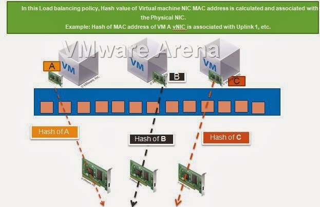
In this load balancing policy, Each Virtual machine outbound traffic will be mapped to a particular physical NIC based on the hash of Virtual Machine NIC’s MAC address. Traffic from a particular virtual NIC is consistently sent to the same uplink adapter unless there is failure of that particular uplink adapter. Even replies are received on the same physical adapter.

Hash of VM A vNIC’s MAC is associated with Uplink 1
Hash of VM B vNIC’s MAC is associated with Uplink 2
Hash of VM C vNIC’s MAC is associated with Uplink 3

Route based on Physical NIC load

This load balancing policy is only available as part of dvSwitch and it is not available in Standard switches. This policy chooses a uplink based on the current load of the physical network adapters. This load balancing policy usea algorithm to perform a regular inspection of load on the Physical NICs every 30 seconds. When the utilization of Particular physical uplink exceeds 75% over 30 seconds, the hypervisor will move VM’s traffic to another uplink adapter. This load balancing doesn’t require any additional configuration at the physical switch level.
This load balancing policy provides better utilization of all the uplink adapters and does perfect load balancing. Please find the below test case results  dvUplinkswith the network bandwidth usage on 2 Uplink adapter during the entire benchmark period. This load balancing policy provides even distribution of network load on both physical uplink adapters.
Graphic Thanks to VMware.com

Use Explicit Failover Order

This setting always use the highest order uplink from the list of Active uplink adapters. In case of failover or both the active uplink adapters failed, Standby adapters will be used. Move the adapters up and down based on the requirement.  uplinks adapters under Unused uplink will not used for the communication.
I hope this is informative for you. Thanks for Reading!!!. Be Social and share it in social media if you feel worth sharing it.

FREE VIDEO TRAINING – VMware vSphere 5.0

VMware Education services has released free training to learn the basics concepts about VMware vSphere 5.0. It covers  the various installation steps including vCenter server and ESXi Server. Configuration of networking including Standard and distributed switches. It also covers the High availability and DRS along with Virtual Machine Administration. It has 13 videos which extensively covers different topics and features about vSphere 5.0

How to Deploy & Configure VMware vSphere Replication 6.5

VMware vSphere Replication 6.5 is the latest version of vSphere Replication (VR) released with vSphere 6.5, vCenter Server 6.5, and Site Recovery Manager (SRM) 6.5. vSphere Replication is a host-based virtual machine (VM) replication solution that works with nearly any storage type supported by VMware vSphere. VR is deployed as a virtual appliance using an Open Virtualization Format (OVF) specification. VMware Site Recovery Manager (SRM) works with two types of replication which are Array Based Replication (ABR) and vSphere Replication. vSphere Replication works closely with VMware Site Recovery Manager. To use vSphere Replication with Site Recovery Manager, We need to deploy vSphere replication appliance to all the Sites where SRM is installed and configured.

I have 2 Datacenter. Out of 2 datacenters, One is Protected site and another one is replicated site. So I need to deploy vSphere Replication application on both sites and integrate with vCenter Server to use it as replication solution. In this article, I will explain the detailed step by step procedure to deploy and configure vSphere Replication 6.5.

How to Deploy & Configure VMware vSphere Replication 6.5

Download the vSphere Replication appliance from VMware website.  As same as other appliance, Login to vCenter Server using vSphere Web client -> Select any ESXi host -> Deploy OVF Template.

When deploying an OVF using the vSphere Web Client, you must select all of the necessary files that go along with the OVF. These include the CERT, MF, OVF, and VMDK files. Note that there are two VMDK files – support and system – both must be included when deploying a VR appliance.

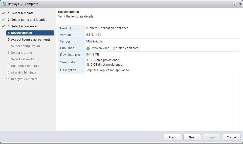
Since it is the standard OVF deployment, I didn’t explain it from the beginning.  Once you reviewed the OVF details. Click Next.

Deploy-and-Configure-vSphere-Replication-6.5_1

Customize the vSphere replication network configuration by specifying the network information for the vSphere Replication. Specify domain name, Gateway address, Subnet mask, management IP address, NTP server information and password for the “root” for vSphere Replication appliance and Click Next.

Deploy-and-Configure-vSphere-Replication-6.5_3

vSphere replication will appear in vSphere Web Client after the deployment to allow the management and replication configuration of virtual machines from Web Client. vSphere Replication appliance requires a binding to the vCenter Extension service, which allows it to register as a vCenter Extension at runtime. Click Next.

Deploy-and-Configure-vSphere-Replication-6.5_4

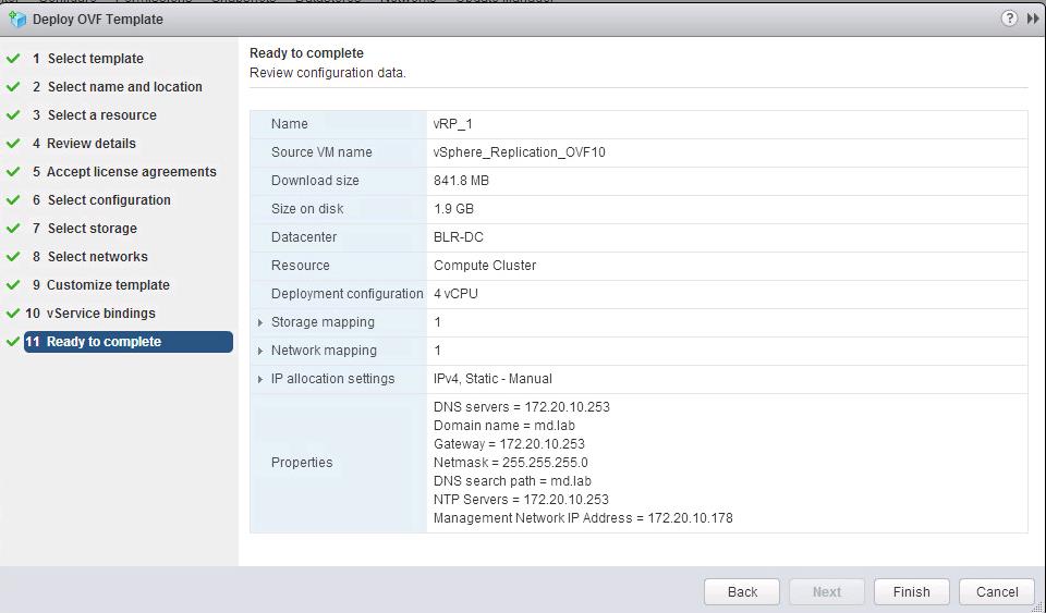
Review all the configuration information and Click on Finish to start the deployment of vSphere Replication.

Deploy-and-Configure-vSphere-Replication-6.5_5

Once VR deployment is completed, access the management URL of the vSphere Replication appliance using below URL format

https://<VR-IP or hostname>:5480

Login with the root user account and password specified during the appliance deployment.

Deploy-and-Configure-vSphere-Replication-6.5_6

To configure to vSphere Replication appliance, Click on VR tab -> Configuration.

In the Lookup Service Address, enter the FQDN of the vCenter Server If your vCenter is embedded PSC deployment else enter the FQDN of the PSC appliance if vCenter is an external PSC deployment. Enter the SSO username and the password for the same. Click Save and Restart services

Deploy-and-Configure-vSphere-Replication-6.5_8

You will be able to see the message “Successfully saved the Configuration” information, Once vSphere Replication appliance is configured.

Deploy-and-Configure-vSphere-Replication-6.5_10

Once vSphere replication is configured, you will be able to see the vSphere Replication plugin start after in vSphere Web Client. You can start managing the replication of virtual machines using vSphere Replication.

Deploy-and-Configure-vSphere-Replication-6.5_11

We need to follow the same procedure to deploy the vSphere replication on another site also.  That’s it. We are done with the deployment and configuration of vSphere Replication. Thanks for Reading!!!. Be social and share it with social media, if you feel worth sharing it.

Comparison between VMware Workstation pro and VMware Workstation player

VMware Workstation Pro and VMware workstation player are the industry standard desktop virtualization for running multiple operating systems as virtual machine on a desktop, laptop or even in your tablet running with windows or linux. Lot of developers, IT professionals and system administrators uses workstation pro and workstation player to run multiple guest operating systems on the single PC or laptop t be more agile, highly productive and more secure. Workstation products allows us to test almost any operating system and application in the local desktop/PC and laptop without need of any additional hardware or servers. In this article, I am going to compare the features between VMware Workstation Pro and VMware Workstation Player. Similar to that, One of the  best comparison article is VMware vs Hyper-V

What is VMware Workstation Pro?

VMware Workstation Pro helps us to create completed isolated, secure virtual machines that encapsulate an operating system and its application. VMware virtualization layer maps the physical hardware resources to the virtual machine’s resources. Each virtual machine running on VMware workstation has its own CPU,memory disks and I/O devices. VMware workstation pro installs on top of the operating system running on your desktop, laptop or tablet running with windows or linux.

VMware Workstation Pro runs on standard x86-based hardware with 64-bit Intel and AMD processors and on 64-bit Windows or Linux host operating systems. VMware recommends 1.2 GB of available disk space for the Workstation pro installation. Additional hard disk space required for each virtual machine.


What is VMware Workstation Player?

VMware Workstation player installs on top of the operating system like any standard desktop application. Workstation player allows you to install new operating systems as virtual machines in a separate window. VMware Workstation Player (formerly known as Player Pro) is a desktop virtualization application that is available for free for personal use. A Commercial License can be applied to enable Workstation Player to run Restricted Virtual Machines created by VMware Workstation Pro and Fusion Pro.

Comparison between VMware Workstation Pro and VMware Workstation Player

Below table compares the features between the VMware workstation pro and VMware Workstation Player.

Comparision-between-VMware-Workstation-pro-and-VMware-Workstation-player-1

I hope this article helps us to understand the basic information between VMware workstation pro and VMware workstation player and also feature comparison between VMware workstation pro and VMware workstation player. Thanks for reading!!. Be social and share it in social media, if you feel worth sharing it.